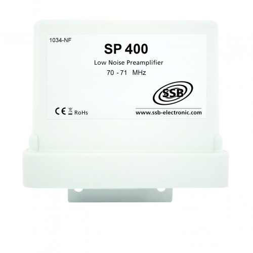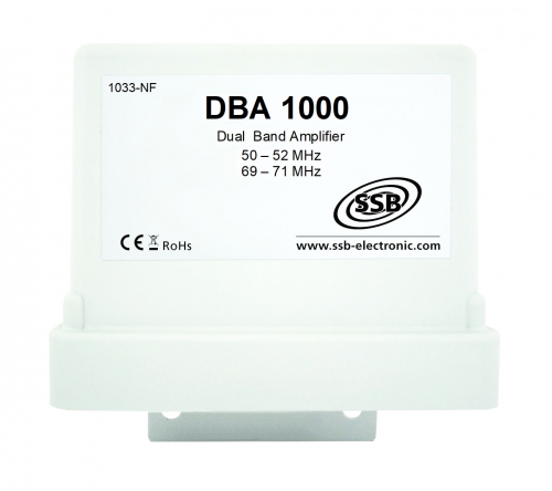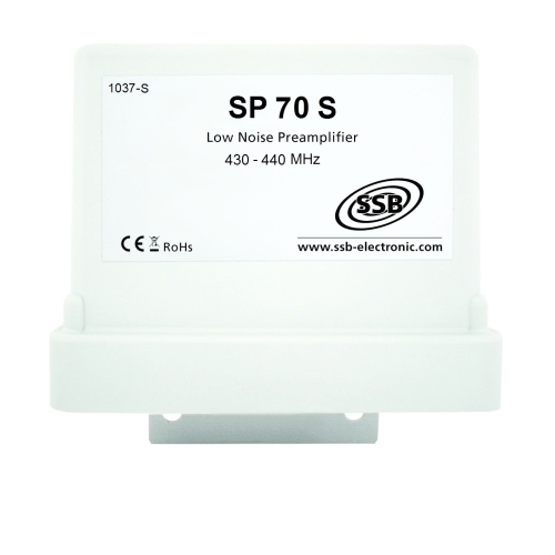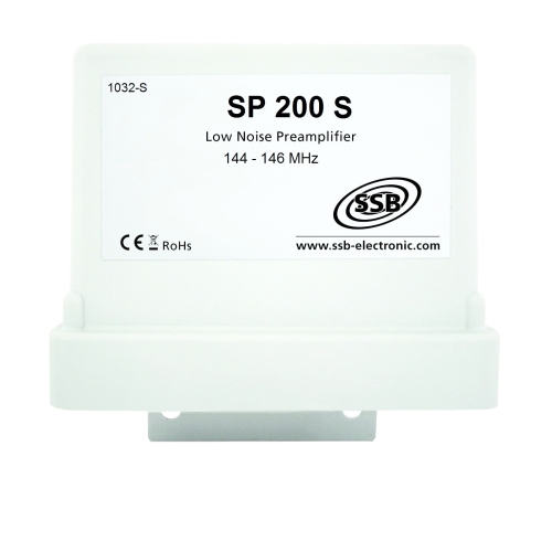
... up to 100W VOX
Super effective, Low-Noise-Preamplifiers with VOX
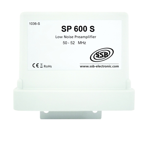
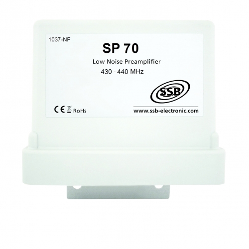
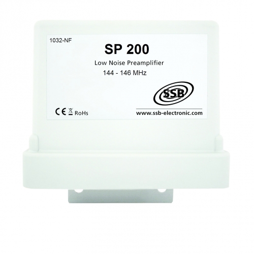
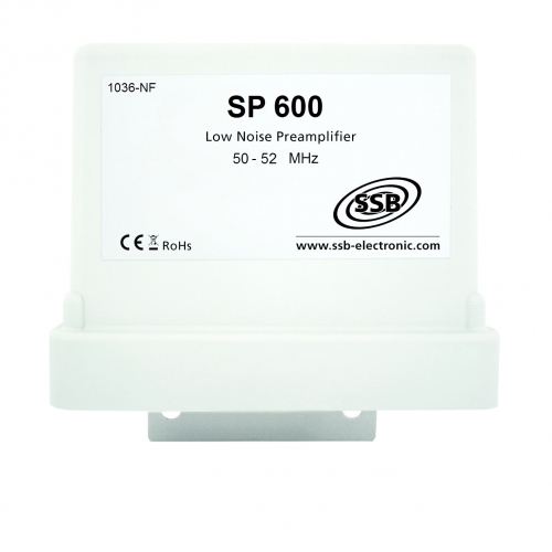
The preamplifiers of the Super-Amp series are available for the amateur radio bands 6 m, 4m, 2 m and 70 cm. All models are equipped with super-low-noise, large-signal-resistant semiconductors which are safeguarded against HF by a an effective protective circuit. To suppress unwanted signals, high quality Helix filters are used.
The Super-Amp amplifiers can be operated alternatively with a remote or direct feed. When a power amplifier is used, we recommend our Sequence Controller of the "DCW" product line. This ensures a timely sequential receive/transmit switchover, controlling the relais load-free, without HF.
The Super-Amp amplifiers are equipped with an UV-resistant, weatherproof housing and N-sockets. Hot-dip galvanized clamps and installation material are part of the delivery. The max. mast diameter is 58mm.
| Technical specification |
SP 600
|
SP 400 |
SP 200
|
SP 70
|
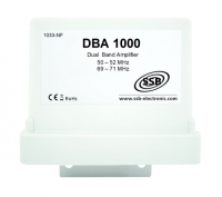
DBA 270 | DBA 1000 |
| Frequency range [MHz]: |
50-52
|
70-71 |
144-146
|
430-440
|
144-146 430-440 |
50-52 69-71 |
| Noise fiigure (20°C) (NF) [dB]: |
0,4
|
0,7 |
0,7
|
1,0
|
1,0 / 2m 1,0 / 70cm |
1,0 / 6m 1,0 / 4m |
| Gain (+/-1%) (S21) [dB]: |
9-18*
|
9-18* |
8-18*
|
13-22*
|
16 / 2 m 24 / 70 cm |
18 / 6m 17 / 4m |
| Switching power with RF VOX PEP [W]: |
200
|
200 |
200
|
200
|
200 | 200 |
| Switching power with RF VOX CW, FM, WSJT, FT8 [W] | 100 | 100 | 100 | 100 | 100 | 100 |
| Transferable power ** PEP [W]: |
750
|
750 |
750
|
500
|
750 | 750 |
| Transferable power ** CW, FM, WSJT, FT8 [W]: |
500
|
400 |
500
|
300
|
400 | 750 |
| Insertion loss [dB]: |
0,03
|
0,04 |
0,04
|
0,15
|
0,1 / 2 m 0,2 / 70 cm |
0,04 |
| Return loss when transmitter is active [dB]: |
50
|
40 |
36
|
35
|
30 / 2 m 40 / 70 cm |
60 / 6 m 45 / 4 m |
| Input return loss (S11) [dB]: | 22 | 24 | 24 | 4,2 | 20 / 2 m 18 / 70 cm |
19 / 6 m 20 / 4 m |
| Output return loss (S22) [dB]: | 22 | 28 | 25 | 26 | 18 / 2 m 18 / 70 cm |
18 / 6 m 28 / 4 m |
| Output IP3 [dBm]: | 21 | 25 | 27 | 20 | 25 / 2 m 27 / 70 cm |
22 / 6m 23 / 4m |
| Input IP3 [dBm]: | 3 | 7 | 9 | -2 | 9 / 2 m 3 / 70 cm |
4 / 6 m 6 / 4 m |
| Operating voltage [V]: |
12-14
|
12-14 |
12-14
|
12-15
|
12-14 | 12-14 |
| Current consumption [mA]: | 260 | 260 | 240 | 330 | 260-280 | 220 |
| Max. mast diameter [mm]: |
58
|
58 |
58
|
58
|
58 | 58 |
| ** when using a sequencer, f. e. DCW 2004 | ||||||
|
* gain is adjustable
|
||||||
Important note on noice figure:
The input and output circuits of the new amplifiers have an exact 50 ohm impedance with very low imaginary components. This ensures that the antenna system is loaded with real 50 ohms and that the parameters of the system are not changed. In the case of highly optimized narrowband antennas that are currently mostly used, it is very important that they are terminated with real 50 ohms. Mismatching at the input of the preamplifier used can lead to a change in the parameters of such antennas, which causes loss of gain and changes in the directional characteristics. Therefore, these amplifiers are optimized for a real 50 Ohm input impedance. This setting produces the best noise figure. In the past, the preamplifiers were optimized for the lowest noise figure. The lowest noise figure is achieved through poor input matching. As a result, the input is no longer terminated with a real 50 Ohm. This mismatch leads to the fact that the real noise figure of the old LNAs is higher than the measured noise figure.
Your opinion counts.
Only in this way we are able to always develop optimum products. We are delighted to receive a feedback from you, where you use these preamps and how satisfied you are with our products! Please write to us: feedback@ssb-electronic.com.
We wish you good reception everywhere with our preamplifiers!

