product description
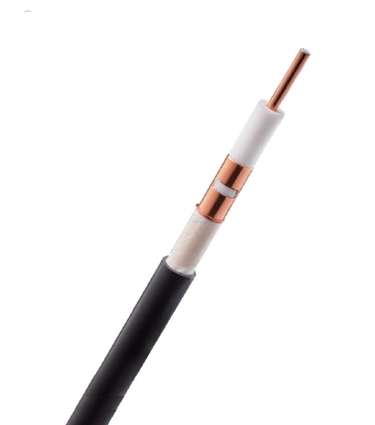
1/2" RADIAFLEX® Radiating Cable
RFS Item Number: RLKU12-50JFLA
>>> Prices and availability on request!FEATURES & BENEFITS
- RADIAFLEX® functions as a distributed antenna to provide communications in tunnels, mines and large building complexes and is the solution for any application in confined areas. Slots in the copper outer conductor allow a controlled portion of the internal RF energy to be radiated into the surrounding environment. Conversely, a signal transmitted near the cable will couple into the slots and be carried along the cable length.
- RADIAFLEX® is used for both one-way and two-way communication systems and because of its broadband capability, a single radiating cable can handle multiple communication systems simultaneously.
- This RADIAFLEX® radiating cable utilize a low-loss cellular polyethylene foam dielectric and a smooth copper outer conductor which offers a superior electrical performance together with good bending properties.
- Ultra wideband from 30 MHz to 2700 MHz
- For applications in tunnels and buildings
- Low coupling loss variations
- Euroclass acc. to EN 50575: Cca s1a d0 a1
MECHANICAL SPECIFICATIONS
| Jacket | JFL | |
| Jacket Description | Halogen free, non corrosive, flame and fire retardant, low smoke, polyolefin + flame barrier tape above outer conductor for lowest cable loss | |
| Slot Design | Groups of vertical slots at short intervals | |
| Inner Conductor Material | Copper Clad Aluminum Wire | |
| Outer Conductor Material | Overlapping Copper Strip | |
| Diameter Inner Conductor | mm (in) | 4.4 (0.17) |
| Diameter Outer Conductor | mm (in) | 11.4 (0.45) |
| Diameter over Jacket Nominal | mm (in) | 14.7 (0.58) |
| Minimum Bending Radius, Single Bend | mm (in) | 200 (7.9) |
| Cable Weight | kg/m (lb/ft) | 0.23 (0.16) |
| Tensile Force | N (lb) | 1300 (292) |
| Indication of Slot Alignment | Bulge atop slots | |
| Recommended / Maximum Clamp Spacing | m (ft) | 0.5 (1.6) |
| Minimum Distance to Wall | mm (in) | 80 (3.15) |
ELECTRICAL SPECIFICATIONS
| Max. Operating Frequency | MHz | 2700 | |
| Cable Type | RLKU | ||
| Impedance | Ohm | 50 +/- 2 | |
| Velocity, percent | % | 88 | |
| Capacitance | pF/m (pF/ft) | 76 (23.2) | |
| Inductance, uH/m (uH/ft) | µH/m (µH/ft) | 0.19 (0.058) | |
| DC-resistance inner conductor | Ω/km (Ω/1000ft) | 1.97 (0.6) | |
| DC-resistance outer conductor | Ω/km (Ω/1000ft) | 4.84 (1.48) | |
| Stop bands | MHz | 650-750, 1330-1430, 2025-2100 | |
| Frequency Selection | MHz | 600, 900, 1800/1900, 2200, 2400, 2500, 2700 | |
TEMPERATURE SPECIFICATIONS
| Storage Temperature | °C (°F) | -70 to 85 (-94 to 185) |
| Installation Temperature | °C (°F) | -25 to 60 (-13 to 140) |
| Operation Temperature | °C (°F) | -40 to 85 (-40 to 185) |
ATTENUATION AND POWER RATING
| Frequency, MHz | Longitudinal Loss, dB/100 m (dB/100 ft) | Coupling Loss 50%, dB | Coupling Loss 95%, dB |
| 75 | 2.17 (0.66) | 49 (53) | 59 (63) |
| 150 | 3.10 (0.94) | 57 (61) | 68 (72) |
| 450 | 5.74 (1.75) | 65 (68) | 76 (79) |
| 800 | 8.75 (2.67) | 57 (59) | 63 (65) |
| 870 | 9.21 (2.81) | 58 (60) | 64 (66) |
| 900 | 9.40 (2.86) | 58 (60) | 63 (66) |
| 960 | 9.73 (2.97) | 58 (60) | 64 (66) |
| 1800 | 21.97 (6.70) | 55 (57) | 65 (67) |
| 1900 | 22.71 (6.92) | 55 (57) | 65 (67) |
| 2000 | 23.48 (7.16) | 53 (56) | 65 (66) |
| 2200 | 25.47 (7.76) | 52 (55) | 60 (63) |
| 2400 | 27.93 (8.51) | 52 (54) | 60 (63) |
| 2600 | 30.50 (9.30) | 52 (54) | 60 (63) |